Modifying the Properties of a Constraint
| This task consists in modifying the mechanical properties and attributes of a constraint. | |||||||||
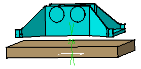
| Open the AssemblyConstraint02.CATProduct document and create an offset constraint. | |||||||||
| 1. | Right-click the offset constraint to
be modified. You can select the constraint in the specification tree or in the geometry. |
||||||||
 |
|||||||||
| 2. | Select Properties from the
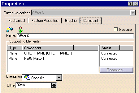
contextual menu. The Properties dialog box that appears displays four tabs. |
||||||||
 |
|||||||||
Constraint tabThe Constraint tab displays the name of the constraint as well as the name and type of the supporting components. You can rename the constraint if desired. The constraint status is also indicated. In our scenario, the constraint is connected. To find out how to reconnect broken or misconnected constraints, please refer to Reconnecting Constraints. |
|||||||||
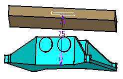
| 3. | Enter a new value in the Offset field. For example, enter 75 mm. | ||||||||
| 4. | Set the Orientation option to Same so as to reverse the blue component. | ||||||||
| Instead of using the Properties contextual command to edit the properties as described above, you can double-click the constraint to be edited to display the related dialog box: in which you can modify the same properties: | |||||||||
|
|
|||||||||
Mechanical tab |
|||||||||
| 5. | Click the Mechanical tab. | ||||||||
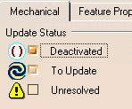
| 6. | Three attributes characterize constraints:
|
||||||||
| 7. | Check Deactivated. The constraint is modified accordingly. |
 |
|||||||
| Note that parentheses precede the constraint value, indicating that the constraint is deactivated. These parentheses precede the name of the constraint in the specification tree too. The color of the graphic symbol is modified. | |||||||||
|
|||||||||
Feature Properties tab |
|||||||||
| 8. | Click the Feature Properties tab. | ||||||||
| This tab displays the constraint's name as well as its creation and last modification date. You can edit the constraint's name. | |||||||||
Graphic tab |
|||||||||
| 9. | Click the Graphic tab. The Graphic tab lets you define the graphic properties of your constraint.
|
||||||||
Select the color of your choice from the list. You can also define your own colors by selecting the More Colors... command at the bottom of the list. To know more about defining personal colors, please refer to CATIA Infrastructure User's Guide. You cannot define a new color for deactivated constraints. For the purposes of our scenario, you need to reactivate the constraint. |
|||||||||
|
|
|||||||||
|
|
|||||||||
| If you wish to change the color for a given status (resolved, unresolved, over-contrained, invalid geometry) use the Tools -> Options command. For more, see Customizing Constraint Appearance. | |||||||||
|
|
|||||||||


