Creating an Angle Constraint
| Line | Plane | Planar Face | Cylinder (axis) |
Cone (axis) |
|
|---|---|---|---|---|---|
| Line |
|
|
|
||
| Plane |
|
|
|||
| Planar Face |
|
|
|||
| Cylinder (axis) |
|
|
|
|
|
| Cone (axis) |
|
|
|
|
|
| This task consists in setting an angle constraint between two planes. | ||||||||||
| Open the AssemblyConstraint03.CATProduct document. | ||||||||||
| Before constraining the desired components, make sure it belongs to a component defined as active (the active component is blue framed and underlined). | ||||||||||
| 1. | Click the Angle Constraint icon This command is also available from the Insert menu. |
|||||||||
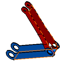
| 2. | Select the face to be constrained, that is the blue face as shown. | |||||||||
 |
||||||||||
| 3. | Select the second face to be constrained, that is the red face in the same direction of the blue face. | |||||||||
|
|
||||||||||
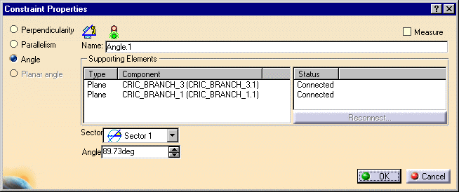
The Constraint Properties dialog box
is displayed with the properties of the selected constraint and the list of available
constraints:
|
||||||||||
 |
||||||||||
| 4. | Keep the Angle option. | |||||||||
| 5. | Enter 40 deg in the Angle field and keep Sector 1. | |||||||||
| 6. | Click OK to create the angle constraint. | |||||||||
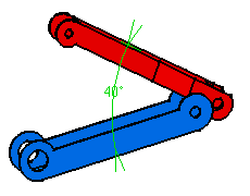
| As the angle constraint is created, the red
component is moved so as to adopt its new position. A green arrow is displayed in the
geometry area to indicate that this constraint has been defined. The angle value is
displayed too. This constraint is added to the specification tree too. |
||||||||||
 |
||||||||||
|
Graphic symbols used for constraints can be customized. For more information, refer to Customizing Constraint Appearance. | |||||||||
