Showing Geometry in Views
| This task will show
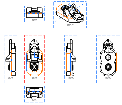
you how to visualize geometrical elements in all viewpoints as well as in
a 3D viewer corresponding to the views analyzed. Note that you can analyze both text/dimension and edge type elements on all the views of a CATDrawing document. These views can be views generated from an assembly, a part or a .model. These views can also be interactive views. |
| Before You Begin, make sure you customized the following settings:
Grid: View names and scaling factors: |
| Open the GenDrafting_part.CATDrawing document.
|
||
| 1. Go to Tools -> Analyze -> Show Geometry in All Viewpoints menu bar command. | ||
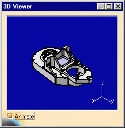
| Provided there is at least one link between the CATDrawing document and a CATPart (or assembly, part or .model) a window appears with the 3D model corresponding to the CATDrawing views. |
|
|
|
2. Move
the cursor over the geometrical elements on one view. |
 |
|
| If the Animate option is on, the part automatically appears with the optimal position (visually speaking). |
|
|
|
||

