Lining up Dimensions (Reference)
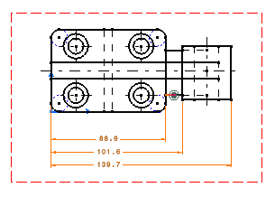
This task will show you how to line up the following dimensions according
to a given reference:
|
|||||||||||
| Open the LineUp_Dimensions02.CATDrawing document. | |||||||||||
1. Go to
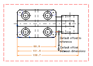
Tools->Options->Mechanical Design->Drafting->Dimensions the offset you can set in this dialog box correspond to : 
|
|||||||||||
|
2. Select the dimensions to be lined-up. 3. Right click and select
Line-up item
from the contextual menu.
|
|||||||||||
| You can also select the select Tools->Positioning->Line-up item from the menu bar. | |||||||||||
|
4. Select the element that will be used as reference for positioning dimensions. See the example above. The Line Up dialog box appears. You can see that the default values are the ones set in Tools Options menu (see step 1).
|
|||||||||||
|
5. Enter the required offset values in the Line Up dialog box and, if needed, deactivate the Only organize into systems option.
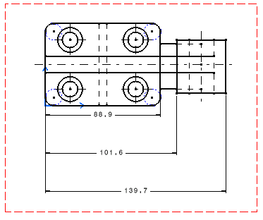
The smallest dimension positions with respect to the element selected and offsets by 20 mm. And offset between dimension is equal to 30mm. 
|
|||||||||||
|
|

