Creating Geometrical Constraints
| This task shows you how to set a relationship that forces a limitation between one or more geometrical elements. | ||
| Before creating a constraint, make
sure the constraint creation option commands are active in the Tools
toolbar.
|
||
| Create two lines.
Make sure the Show Constraints command
|
||
| 1. Select the geometrical elements to be
constrained to each others, for example two lines to be set as parallel lines. 2. Click the Constraint with Dialog Box icon
The Constraint Definition dialog box appears. 3. Modify the Constraint Definition dialog box. For example, activate the Parallelism switch.
|
 |
|
 |
||
| It is impossible to
create constraints between 2D and generated elements via the
Constraint Definition dialog box. In the Constraint Definition
dialog box, you can only create constraints between similar elements. In
other words, you can create constraints either between 2D elements, or
between generated elements, but not between a mix of these.
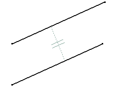
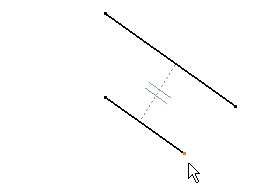
4. Click OK. Both lines are now parallel to each others. 5. Modify the position of one geometrical element. For example, move one end point on one line. |
||
 |
 |
|
| The lines are driven so as to remain parallel to each others whatever the new position and/or length you assign to one of them. | ||
| Even though you set a constraint relation between two
elements, constraints are not necessarily visualized. Check the Show Constraints |
||
|


