Creating Rotation Forces
| Rotation Forces
are intensive loads representing
mass body force (acceleration) fields induced by rotational motion applied to
parts. Rotation Force objects belong to Loads objects sets. The user specifies a rotation axis and values for the angular velocity and angular acceleration magnitudes, and the program automatically evaluates the linearly varying acceleration field distribution. Units are angular velocity and angular acceleration units (typically rad/sec and rad/sec2 in SI).
|
|||||||||||||||||
Rotation Forces can be applied to the following types of
Supports:
|
|||||||||||||||||
| This task shows you how to
create a Rotation Force applied to a part.
|
|||||||||||||||||
|
You can use the sample00.CATAnalysis document from the samples directory for this task: Finite Element Model containing a Static Analysis Case and computed corresponding Static Solution. Before You Begin:
|
|||||||||||||||||
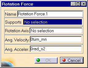
| 1. Click the Rotation icon The Rotation Force dialog box is displayed.
2. You can change the identifier of the Rotation Force by editing the Name field. 3. Select the geometry support (Supports field): the part on which the variable acceleration field is to be applied. Any selectable geometry is highlighted when you pass the cursor over it.
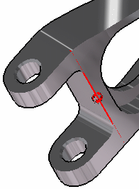
You can select several supports in sequence, to apply the Rotation Force to all supports simultaneously. 4. Select an existing line or a construction axis to specify the Rotation Axis. Any selectable geometry is highlighted when you pass the cursor over it.
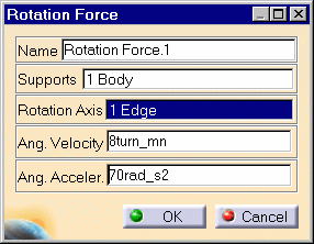
To select a User-defined Axis system, you must activate an existing Axis by clicking it in the features tree. Its name will then be automatically displayed in the Axis Name field. Symbols representing the Rotation Force are displayed on the support geometry to visualize the acceleration field. 5. Enter a value for the magnitude of the Angular Velocity about the rotation axis. For example, 8turn_mn. 6. Enter a value for the magnitude of the Angular Acceleration about the rotation axis. For example, 70rad_s2.
A Rotation Force object appears in the specification tree under the active Loads objects set.
|
|||||||||||||||||
|
|
|
||||||||||||||||
| Make sure the computation is finished before
starting any of the below operations.
|
|||||||||||||||||
|
|
Products Available in Analysis Workbench The ELFINI Structural Analysis product offers the following additional features with a right mouse click (key 3):
|
||||||||||||||||
|
|||||||||||||||||
|
|
|||||||||||||||||


