 |
Images can be generated into images that are not those
included in the Image toolbar (Image Choice dialog
box). The list of these images will depend on
the Case type. You will then be able to edit different
types of images that by default appear in the Image Choice dialog box.
In other words, the names of the images depend on:
- a physical type (for example, displacement)
- a visualization type (for example, Symbol or Text)
- as well as a criterion (for example, Vector or Principal value).
|
 |
This task shows how the various options are provided so that
you may get the desired image.
|
 |
You can use the sample03.CATAnalysis
document from the samples
directory for this task. Before You Begin:
 | Create the following images:
Deformed  , Stress Von Mises Stress
  and Principal Stresses
  . . |
 | Activate the desired image:
Right-click the desired generated image from the
specification and select the Activate/Deactivate option displayed in the
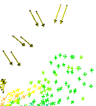
contextual menu. In this case, you will activate the Stress Principal tensor
symbol image. |
|

|
1. Double-click the Stress Principal tensor
symbol image from the specification tree.
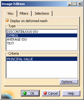
The Image Edition dialog box appears:
|

|
|
|
2. Select the desired options from
the Image Edition dialog box. As an example, select the options as set
below.
The following basic options are provided in tabs:
|

|
Visu Tab

|
|
Type
Provides a list with visualization types (how):
- DISCONTINUOUS-ISO
- SYMBOL
- AVERAGE-ISO
- TEXT
- FRINGE (available in the case of a Pressure Fringe
image generated from a Pressure load)
Criteria
Provides a list with visualization criteria (what mathematical object type)
The list can be very long. We therefore
decided to include here only the options available when generating a
Stress principal tensor component image with AVERAGE-ISO Visu type:
- VON-MISES
- PRINCIPAL-SHEARING
- PRINCIPAL-VALUE
- ABS-PRINCIPAL-VALUE
- TENSOR-COMPONENT
|

|

|
|
As you change the Visu and Criteria option types, the image object
in the specification tree is modified.
Options
 Provides the possibility to define Visualizations options (only available if you installed the ELFINI Structural Analysis
product). For this,
select the Options... button . The Options dialog box that
appears depends on the Type option previously selected.
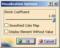
 | DISCONTINUOUS-ISO: The Visualization Options
dialog box now appears. |
|
|
- Smooth Color Map: distribute a larger number of colors
- Display Elements Without Value: display elements with or
without value.
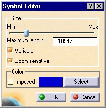
 | SYMBOL: The Symbol Editor
dialog box now appears. |
|
|
- Maximum length: define the arrow length
- Variable: enable the variability of the symbols
- Maximum length: enable the length of the symbols to be zoom
sensitive
- Imposed: enable the color to be fix
- Select: enable the color chooser panel dialog box
 | AVERAGE-ISO: The Visualization Options dialog box now appears. |

|
|
- Smooth Color Map: distribute a larger number of colors
- Display Elements Without Value: display elements with or
without value.
 | Text: No options available. |
 | FRINGE: The Visualization Options dialog box now appears. |

- Smooth Color Map: distribute a larger number of colors
- Display Elements Without Value: display elements with or
without value.
|

|
Filters tab (what)
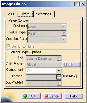
Provides different Value Control and Element Type
Options filters:
Value Control
|
| |
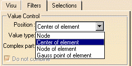
Position: in this particular case, you can
choose to generate images on:
- Node: single available option in the case of images generated
with the AVERAGE-ISO Visu mode (all types of images)
- Center of element
- Node of element: single available option in the case of
images generated with the DISCONTINUOUS-ISO Visu mode (all types of
images)
- Gauss point of elements
You may also have the options below available:
- Face of element: available in the case of a Pressure Fringe
image generated from a Pressure load.
- Edge of element: available in the case of a Line force
vector image generated from a Line Force Density load.
Value Type: corresponds to the type of the value:
integer, real, double precision, complex, complex with double precision
and so forth.
Complex part: the complex part available when the
type of the value is complex.
|

|
Do not combine:
If this option is not activated, combined values will be displayed whenever available.
The desired resulting force will be displayed.
If this option is activated, each specification (force, restraints and
so forth) can be displayed separately. You will use the Value
set combo box to choose the desired value set. Note that the ALL combination is only available in the case
of symbols.

For example, if three forces were applied on a single surface, three
values will be available in the Value set combo box. You can
then select the desired Value set.
Element Type Options
|

|
For: change the element type to be filtered
Axis System: select the current axis system to be
used
|
| |
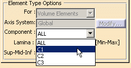
Component: in this particular case, if you select a Principal tensor
image, TEXT Visu option, PRINCIPAL-VALUE criteria,
you will get the Position options above
|
| |
In this particular case, you can
choose to generate images with:
ALL: all the components
C1: components according to x in the current axis system
C2: components according to y in the current axis system
You may also have the options below available:
C3: components according to z in the current axis system
You can also have a combination of these components (for example, C1C2).
|
 |
For Stress principal tensors,
- In the case of Volume elements:
C1: is the maximum principal stress
C2: is the middle principal stress
C3: is the minimum principal stress
- In the case of Surface elements:
C1: is the maximum principal stress
C2: is the minimum principal stress
|
| |
Lamina: (only available in the case of surface
elements)
You can select the lamina from which the results will be computed.
Sup-Mid-Inf: (only available in the case of
surface elements)
In a lamina, you can select the sub-layer from which the results will be
computed.
|
 |
Sensors vs Images
When creating sensors in the case of surfaces composed of
several laminas and/or several layers, Minimum and Maximum values are computed taking into
account all the laminas or layers. This is why the max value displayed
in the color palette does not necessarily correspond to the max value
displayed when creating a sensor.
|
| |
Selections tab 
Either all or, in the
case of CATProducts, pre-defined groups of elements belonging to given
mesh parts or linked to a given boundary condition specification
(restraint, load, mass and so forth) can be multi-selected. In other words, given elements
associated to a mesh part are automatically grouped and you can multi-select
these groups (only available if you installed the ELFINI Structural Analysis
product). |

|

|
|

|


