Creating Adaptivity Boxes
| The Finite Element Mesh is the
collection of Nodes and Elements used to represent the system in order to
transform the continuous mechanical problem into a discrete numerical
problem.
A finer mesh is expected to produce better results than a coarse mesh, but at a higher cost (more Memory and Time required to generate the results). This is also true locally: results are more precise in a region where the mesh is refined. Adaptivity consists in selectively refining the mesh in such a way as to obtain a desired results accuracy in a specified region. The mesh refining criteria are based on a technique called predictive error estimation, which consists of determining the distribution of a local error estimate field for a given Static Analysis Case. Adaptivity Boxes are local specifications relative to the maximum error in the approximate computed solution relative to the exact solution.
|
|||||
| This task shows how to
create an Adaptivity Box on a Mesh Part for a given Static Analysis Case
Solution.
|
|||||
|
You can use the sample00.CATAnalysis document from the samples directory for this task: Finite Element Model containing a Static Analysis Case and computed corresponding Static Solution. Before You Begin
|
|||||
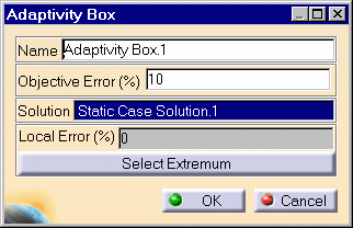
| 1. Click the Adaptivity Box icon The Local Adaptivity Box dialog box is displayed. You can change the name by editing the Name field. 2. If needed, enter a target percentage error in the Objective Error field.
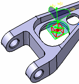
A cuboid symbol representing the Adaptivity Box is displayed on the part.
|
|||||
|
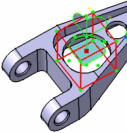
You can modify the location and dimensions of the Adaptivity Box by dragging the control points at the centers of the box faces. You can use the compass concurrently to orient the directions in which
you modify the box. As you modify the Adaptivity Box, the corresponding local error % value displayed in the Local Error(%) field is correspondingly updated.
|
|||||
| 3. Click OK to create the Adaptivity
Box. A symbol representing the Adaptivity Box is visualized on the support. An Adaptivity Manager objects set, containing a Convergence Manager objects set and an Adaptivities.1 objects set appears in the features tree under the FEM Model. An Adaptivity Box.1 object appears in the features tree under the active Adaptivities.1 objects set.
|
|||||
|
|
Products Available in Analysis Workbench
You can create several Adaptivity Box objects associated to different Static Solutions and corresponding to different regions of your part. In particular, you can:
|
||||
| To further edit the Adaptivity Box objects, simply right-click on the Adaptivity Box object (key 3) and select .object -> Definition, or double-click the Adaptivity Box symbol in the features tree. | |||||
|
|||||


