Entering the Structural Analysis Workbench
| This first task will show you how to load a
.CATPart document (and display the corresponding specification tree) by entering
the Generative Structural Analysis workbench and defining that you will create a Static
Analysis case.
Creating a static analysis case means that you will analyze the static boundary conditions of the CATAnalysis document one after the other.
|
|||||
Before you begin:
|
|||||
|
|
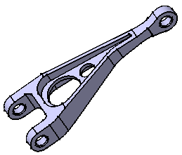
Open the CATPart Document1. Select File -> Open, then select the desired .CATPart file. In this tutorial, you will open CATPart named sample01.CATPart. This opens a Part Design document containing the selected part.
|
||||
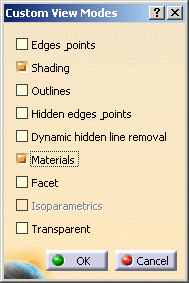
Define the View Mode2. Select View -> Render Style -> Customize View option from the toolbar and activate the Materials option from the displayed Custom View Modes dialog box.
|
|||||
Enter Generative Structural Analysis Workbench3. Select Start -> Analysis & Simulation ->
Generative Structural Analysis from the menu bar. The New Analysis Case dialog box appears with Static Analysis as default type.
|
|||||
 Frequency Analysis means that you will analyze the
dynamic boundary conditions of the CATAnalysis document . Frequency Analysis means that you will analyze the
dynamic boundary conditions of the CATAnalysis document . |
|||||
Keep as default starting analysis case means that when you next open the Generative Structural Analysis workbench from the menu bar, the selected case appears as default.
|
|||||
| 4. If needed, select an Analysis Case type
from the New Analysis Case dialog box. In this particular case, also keep Static Analysis type selected. 5. Click OK in the New Analysis Case dialog box to enter the workbench. The CATAnalysis document now opens. It is named Analysis1. You will now perform different operations in this document.A link exist between the CATPart and the CATAnalysis document.
|
|||||
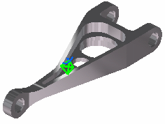
| Double-clicking on the green symbol allows displaying mesh
specifications or setting meshing parameters.
The standard structure of the Analysis specification tree is displayed. As you can see below, the Finite Element Model contains a Static Case, which contains empty Restraints and Loads objects sets, along with an empty Static Case Solution.1 object set. All along this tutorial, you will assign a Restraint and a Load to the CATAnalysis document and then compute the Static Case Solution.
|
|||||
|
|||||


