Creating PowerCopies
| This task shows how to create
PowerCopy elements, to be reused later. A PowerCopy is a set of features (geometric elements, formulas, constraints and so forth) that are grouped in order to be used in a different context, and presenting the ability to be completely redefined when pasted. This PowerCopy captures the design intent and know-how of the designer thus enabling greater reusability and efficiency. |
||||
| Open the PowerCopyStart.CATPart document. | ||||
| 1. | Select the Insert ->Advanced Replication
Tools -> PowerCopy Creation
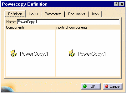
menu item. The Powercopy Definition dialog box is displayed. |
|||
|
|
||||
| 2. |
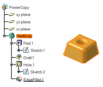
Select the elements making up the PowerCopy from the specification tree. For the purposes of our scenario, select "Part Body". |
|||
 |
||||
|
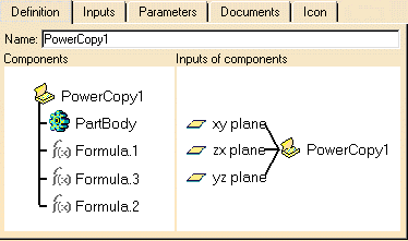
The dialog box is automatically filled with information about the selected elements. |
||||
 |
||||
| 3. | Define the PowerCopy as you wish to
create it:
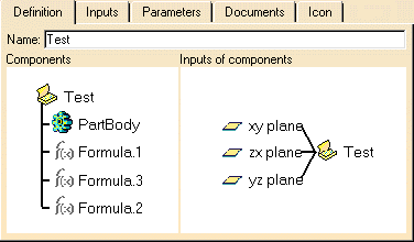
The Definition tab lets you assign a name to the powercopy and presents its components in the 3D viewer. For example, enter "Test" in the Name: field. |
|||
|
|
||||
| 4. |
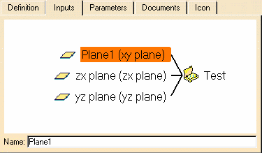
The Inputs tab lets you define the reference elements making up the PowerCopy. You can rename these elements for a clearer definition by selecting them in the viewer and entering a new name in the Name field. In parentheses you still can read the elements' default name based on its type. For example, select xy plane and rename it as "Plane1". |
|||
|
|
||||
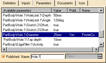
| The Parameters tab lets you define which of the parameter values used in the PowerCopy you will be able to modify at instantiation time. This can be a value, or a formula for example. | ||||
| 5. |
Simply select the parameters and check the Published button. In case of a formula, you can set it to false or true. For example, select PartBody\Hole.1\Diameter Use the Name field to give a more explicit name to this element. For example, enter "Hole.1". |
|||
|
|
||||
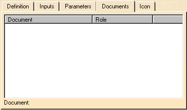
| The Documents tab shows the complete path and role of Design tables that are referenced by an element included in the Power Copy. | ||||
|
|
||||
| 6. |
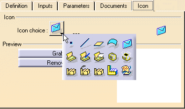
The Icon tab lets you modify the icon
identifying the PowerCopy in the specifications tree. A subset of icons is
available from the Icon choice button. If you click ... the Icon Browser opens, showing all icons loaded on
your CATIA session. Click the envelope icon |
|||
|
|
||||
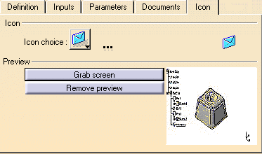
| 7. | The Grab screen button lets you capture an image of the PowerCopy to be stored with its definition. Click the Grab screen button. You can zoom in or out the image to adjust it. | |||
|
|
||||
| 8. | Click the Remove preview button if you do not need this image. | |||
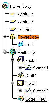
| 9. | Click OK to create the PowerCopy.
The PowerCopy is displayed close to the top of the specification tree. |
|||
|
|
||||
|
||||
|
||||
A Few Recommendations |
||||
|
||||
|
||||
|
||||
|
|
||||
|
||||
|
|
||||
|
||||
|
||||
|
||||
|
||||
|
|
||||
