Editing Parts, Bodies and Features
| Editing a part may mean for example modifying the density of the part (See
Displaying and Editing Properties
), but most often editing consists in modifying the
features composing the part. This operation can be done at any time. There are several ways of editing a feature. If you modify the sketch used in the definition of a feature, CATIA will take this modification into account to compute the feature again: in other words, associativity is maintained. Now, you can also edit your features through definition dialog boxes in order to redefine the parameters of your choice. |
Redefining Feature Parameters
| This task shows how to edit a draft and a pad. The process described here is valid for any other feature to be edited. | |||
| Open the Edit1.CATPart document. | |||
| 1. | Double-click the draft
to be edited (in the specification tree or in the geometry
area). The Draft Definition dialog box appears and the application shows the current draft angle value. Generally speaking, the application always shows dimensional constraints related to the feature you are editing. Concerning sketch-based features, it also shows the sketches used for extrusion as well as the constraints defined for these sketches. |
||
 |
 |
||
| Instead of double-clicking the element you wish to edit, you can also click this element and select the XXX.object -> Definition... command which will display the edit dialog box. | |||
| 2.
3. |
Enter a new draft angle value.
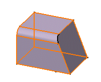
Click OK. This is your new feature: |
||
|
|
|||
| 4. | Now, double-click the pad. The Pad Definition dialog box appears and the application shows the pad only, not the next operation. You will notice that the pad was created in symmetric extent mode and that the application displays information about the initial profile. |
 |
|
| 5. | Enter a new length value. | ||
| 6. | Uncheck the Mirrored extent option. | ||
| 7. |
Enter a length value for the second limit in the Length field. The application previews the new pad to be created. |
||
| 8. | Click OK. The modifications are taken into account. Your part now looks like this:
|
 |
|
|
1. | You can also access the parameters you wish to
edit in the following way:
Select the feature in the specification tree and use the feature.n object -> Edit Parameters contextual command. You can now view the feature parameters in the geometry area. |
|
| 2. | Double-click the parameter of interest. A small dialog box appears displaying the parameter value: |
 |
|
| 3. | Enter a new value and click OK. | ||
|
|
|||
