Analyzing Degrees of Freedom
![]()
| This task explains how to see if you need to set additional constraints to the components making up your assembly. | ||
| Open the AnalyzingAssembly04.CATProduct document. | ||
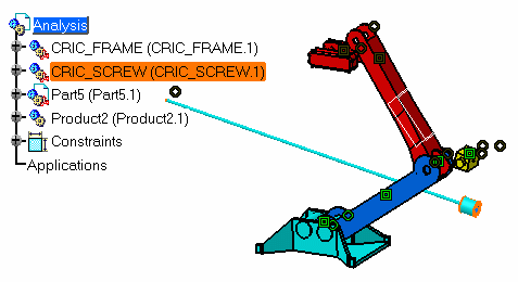
| 1. | Double-click CRIC_SCREW (CRIC_SCREW.1) to make it active. | |
|
||
| 2. | Select the Analyze -> Degrees of Freedom command. | |
|
|
||
| The dialog box
displays all rotations and translations that remain possible for the selected component.
In our scenario, you can
rotate CRIC_SCREW (CRIC_SCREW.1) in three ways or translate it in two
ways.
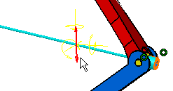
If you look at the geometry, you can notice that these rotations and translations are represented in yellow. |
||
| 3. | Click the button Rotation_2. The graphic element representing this possible rotation is now highlighted in the geometry for easy identification. | |
|
|
||
| As detailed in the dialog box, you can perform a rotation around the vector which coordinates are x=0, y=1 and z=0 and using the point with coordinates x=0, y=0 and z=0 as the rotation center. | ||
| 4. | Click Translation_2. The graphic element representing this possible rotation is now highlighted too. | |
|
|
||
| As detailed in the dialog box, you can perform a translation along the vector which coordinates are x=0, y=0 and z=1. | ||
| 5. | Click Close to exit the command. | |
|
|
||


