Filtering Dimension Generation
| Before you begin, make sure you customized the following settings:
Dimension generation:
|
||||||||||||||||||||||
| This task will show you how to set filters before dimension
generation using the Dimension Generation Filters dialog box.
|
||||||||||||||||||||||
| Open the GEAR-REDUCER.CATProduct and
the GEAR-REDUCER.CATDrawing
documents.
Tile your windows horizontally to view both your drawing and the related part. To do this, select Window -> Tile Horizontally from the menu bar.
|
||||||||||||||||||||||
| 1. By default,
dimensions will be generated on all views. If you want to generate
dimensions on a specific view, select this view.
2. Click the Generating Dimensions icon |
||||||||||||||||||||||

|

|
|||||||||||||||||||||
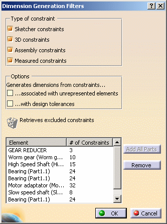
| The Dimension Generation Filters dialog box is automatically displayed. | ||||||||||||||||||||||
 |
||||||||||||||||||||||
The Dimension Generation Filters dialog box displays the parameters and filters that you can use for dimension generation, lists the elements for which dimensions will be generated, and specifies how many constraints there are for each listed element. Let's describe the dialog box more precisely: Type of constraint These options let you specify what type of constraints you want to generate dimensions from in your drawing.
Options These options let you generate additional dimension types.
Other
By default, only the product is displayed in the list of elements for which dimensions will be generated, and only the Assembly constraints and Measured options are active: if you left the dialog box as is, dimensions would only be generated from the product assembly constraints and measured constraints. 3. You will now add additional elements to generate dimensions for. You have two possibilities:
|
||||||||||||||||||||||
|
|
||||||||||||||||||||||
For the purpose of this exercise, click the Add all parts button. All elements are added to the list. You can notice that the Sketcher constraints and 3D constraints options are now active and selected. |
||||||||||||||||||||||

|
||||||||||||||||||||||
|
When the same part is used several times within a given product (as is the case for Bearing (Part1.1) in this scenario), generations for this part are generated only once, for a single part instance (instead of being generated for all part instances). By default, dimensions are generated on the part instance which is the first in the product specification tree. If you want to generate dimensions on a specific part instance, you need to select this instance. 4. Unselect the 3D constraints option to specify that dimensions from 3D constraints should not be generated. You can notice that the list is updated with the proper number of constraints for each element. |
|||||||||||||||||||||

|
||||||||||||||||||||||
| 5. Click OK. The dimensions are generated on the drawing. | ||||||||||||||||||||||
|
||||||||||||||||||||||
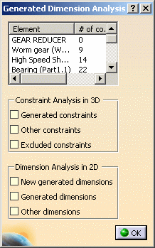
| Depending on whether the Analysis after generation option was selected in Tools->Options, the Generated Dimension Analysis dialog box may now appear. | ||||||||||||||||||||||

|
||||||||||||||||||||||
|
5. Click OK to close the Generated Dimension Analysis dialog box. |
||||||||||||||||||||||
|
||||||||||||||||||||||


