Creating Views Using Folding Lines
| This task will show you how to add geometry in views using folding lines as an assistant. This is true for any kind of view, as long as the planes they correspond to are not parallel. For example, you cannot have folding lines between a front view and a rear view. | ||
| Open the IntDrafting_Views_FoldingLines.CATDrawing document. Go to Tools->Options->Mechanical Design->Drafting (General tab) and deactivate the Grid display option from the dialog box.
|
||
| Make sure the view in which you are going to create geometry using folding lines is active. | ||
|
|
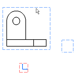
1. Right-click the view to
used as reference. 2. Select the object
->Show folding Lines option |
 |
| In the case of more complex geometry, you can select one or more element(s) in the reference view and display the corresponding folding lines. As a result, the views are not overloaded with folding lines. | ||
| This is also true in the case of 2D components. | ||
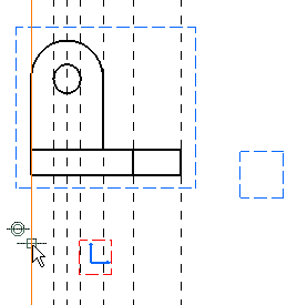
| The folding lines appear. |  |
|
| At any time, you can right-click the view and suppress these folding line using the |
||
| 3. Click the Profile icon |
||
 |
 |
|
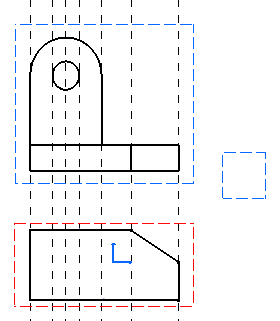
| What you are now going to do is create geometry in the left view, of course using folding lines. | ||
| 4. Right-click the
left view in which you are going to create
geometry and select the |
 |
|
| The folding lines disappear. 5. Right-click both non active
views one after the other and select the |
||
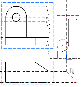
| The folding lines now appear as shown here: | 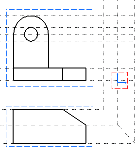 |
|
| 6. Click the Profile icon |
 |
|
| 7. Click a view and move it. Even when views are not aligned, folding lines remain associative. |
||
 |
||
| All the above described functionalities are also true in the case of views with a different scale. | ||