 |
|
This task will show you how to create a
chamfer
dimension. |
 |
|
Open the IntDrafting_Dim_Chamfer.CATDrawing
document.
|
 |
1. |
Click the
Chamfer Dimension icon  from the Dimensioning toolbar (Dimensions subtoolbar).


|
|
2. |
In the toolbar Tools, you can choose:

 | The format of the dimension:
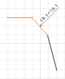
 | Length x Length, in the example 19,1 x 19,1 |
 | Length x Angle, in this example 19.1 x - 46°84'8" |
 | Angle x Length, in this example - 46°84'8" x 19.1 |
 | Length 19,1. |
|
 | The representation mode:
|
Choose Length x Length format and one symbol mode  . . |
 |
|
 | Text, dimension and graphic Properties Toolbars settings are taken
into account during creation, |
 | All settings defined in Tools->Option->Mechanical
Design->Drafting (Dimension and Manipulators tabs) are taken
into account during creation. |
|
|
3. |
Select the element to be
dimensioned.
|

|
| 4. |
Select a reference line or surface. |
| 5. |
Click on the sheet to end the dimension
creation.
The chamfer dimension is computed with an implicit second reference line
that is perpendicular to the first one. |
|
5. |
OR
Select a second
reference line or surface.
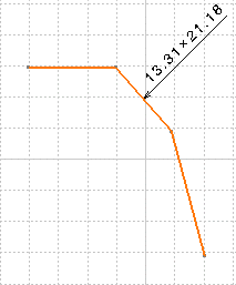
In this case, the value of the chamfer dimension is computed according to
both reference lines.
|

|
 |
|
In any case, the dimension is associated to all the selected
elements.
|

|
 |
|
 | When creating a chamfer dimension on a generated view, all elements you select must belong to a plane which is normal to
the projection plane. |
|
|
|
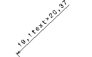
 | When editing chamfer dimension text properties (Edit > Properties
command, Dimension Texts tab), if you assign a suffix to the main
value, or if you insert a text after the main value, the text will
actually be placed after the first value, as shown here. |
|
 |
|

|


