Visualizing Principal Stresses
| Stress principal tensor symbol images are used to
visualize principal stress field patterns, which represent a tensor
field quantity used
to measure the state of stress and to determine the load path on a loaded
part. Stress principal tensor symbol Image objects belong to Static Case Solution objects sets. At each point, the principal stress tensor gives the directions relative to which the part is in a state of pure tension/compression (zero shear stress components on the corresponding planes) and the values of the corresponding tensile/compressive stresses.
|
|||||||||||||||||||||
| This task shows how to
generate Stress principal tensor symbol images on part geometries.
|
|||||||||||||||||||||
You can use the sample24.CATAnalysis document. Before You Begin:
|
|||||||||||||||||||||
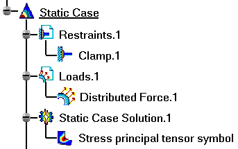
| 1. Click the Principal Stress icon The Stress principal tensor symbol image is displayed, and a Stress principal tensor symbol Image object appears in the specification tree under the active Static Case Solution objects set.
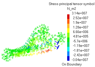
You can visualize the Stress principal tensor symbol image in different ways by modifying the Custom view modes. To do this, you open the View menu and select Render Style -> Customize View option. The principal values stress tensor distribution on the part is visualized in symbol mode, along with a color palette:
2. When the mouse cursor is passing over tensor symbol representations, their principal values are displayed.
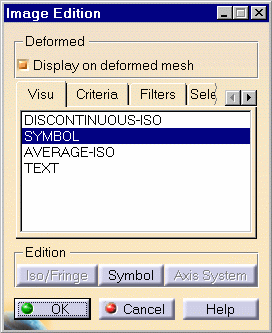
4. Double-click the Stress principal tensor symbol object in the
specification tree to edit the image.
and the following tabs:
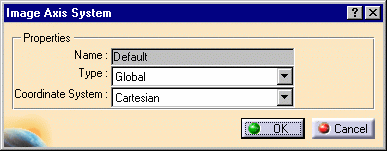
As you change the Visu option type, the name of the Stress principal tensor symbol object in the specification tree is modified (the option type is appended to the name). In addition, the following buttons are available:
5. Click OK to exit the different dialog boxes. You can use the right mouse click (key 3) on a Stresses Principal tensor feature in the specification tree and select the option called Activate / Deactivate to turn the corresponding image on or off.
|
|||||||||||||||||||||
| Products Available in
Analysis Workbench
The ELFINI Structural Analysis product offers the following additional features with a right mouse click (key 3) on a Stresses Principal tensor object: Report: This icon generates a report in .html and .txt formats.
|
|||||||||||||||||||||
|
|||||||||||||||||||||


