Checking the Model
| We advise that you perform a check before computing a case. | |||||||||||
This task lets you know how to check
whether specification assigned to a model are consistent. You can perform
check operations on:
|
|||||||||||
| Note that this check on features considered as inconsistent is performed
both via the dialog box (one line per feature and a dedicated diagnostic
box) and via highlighted associated features in the specification
tree.
|
|||||||||||
Check on BodiesCheck on bodies means on all the Mesh parts (1D, 2D, 3D) as well as their properties and supports. Scenario1: You created a new propertyFor this, you selected the Solid Property command and selected pad1.
|
|||||||||||
| Open sample37.CATAnalysis
document.
|
|||||||||||
| 1. Click the Model Check icon |
|||||||||||
|
The Model Check dialog box appears with the following tabs:
|
|||||||||||
|
|
||||||||||
|
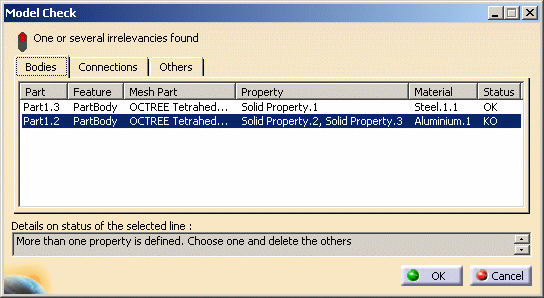
The Model Check dialog box displays all the parts (one per line in the dialog box) which are assigned at least one mesh part or property. A status is assigned to each Mesh part you select in the dialog box, to let you know whether:
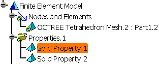
When you select a part in the table, the corresponding features in the specification tree and in the model as well as the assigned properties and material are also highlighted. In this particular case, more than one property has been defined. 2. Click OK to leave the dialog box. 3. Delete the property you do not need and get this:
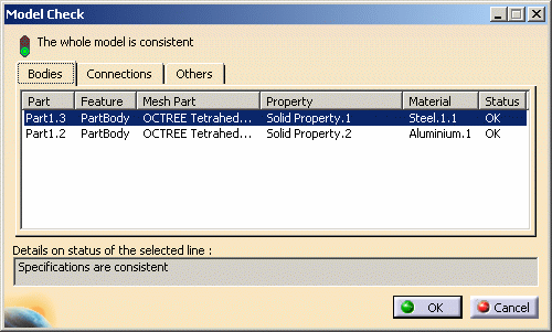
4. Click the Model Check icon The specifications are now consistent: all the states are set to OK.
|
|||||||||||
|
5. Click OK to leave the dialog box. |
|||||||||||
Scenario2: You deleted the material from an OCTREE mesh part |
|||||||||||
| Open sample38.CATAnalysis
document.
|
|||||||||||
| 1. Click the Model Check icon |
|||||||||||
|
The Model Check dialog box appears with the following tabs:
|
|||||||||||
|
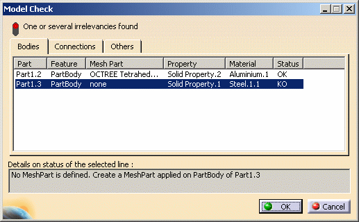
The Model Check dialog box displqys the lists of all the Mesh parts as well as their properties and supports.
A status is assigned to each Mesh part to let you know whether:
When you select a part in the table, the corresponding features in the specification tree and in the model as well as the assigned properties and material are also highlighted. In this particular case, No Mesh Part is defined 2. Click OK to leave the dialog box. 3. Create a mesh part applied on PartBody of Part1.3 and get this:
4. Click the Model Check icon The specifications are now consistent: all the states are set to OK.
5. Click OK to leave the dialog box. |
|||||||||||
|
|||||||||||
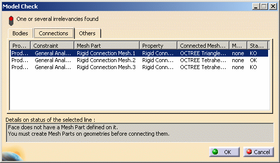
Check on ConnectionsCheck on connections means on any connection specification. In other words, you will check the consistency of the connections regarding the following: missing mesh parts, properties, materials ; connected supports with no associated mesh parts ; overlapping connections and so forth. Scenario: You deleted the mesh part of a part that was connected to another
|
|||||||||||
| Open sample50.CATAnalysis document.
|
|||||||||||
| 1. Click the Model Check icon |
|||||||||||
|
The Model Check dialog box appears with the following tabs:
|
|||||||||||
The Model Check dialog box and Connection tab display all the parts (one per line in the
dialog box) which are assigned at least one connection:
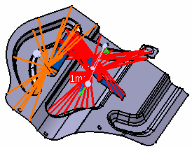
When you select a connected mesh part in the table, the corresponding features in the specification tree and in the model as well as the assigned properties, material and constraints are also highlighted.
In this particular case, Face does not have a Mesh Part defined on it. 2. Click OK to leave the dialog box. 3. Create mesh parts on the geometry. |
|||||||||||
|
|||||||||||
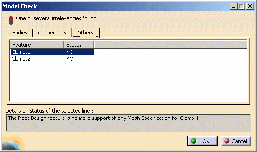
Check on OthersCheck on others means on specification features such as loads, restraints, virtual parts, masses and periodic conditions. Scenario: You deleted the mesh part of a clamped part that was connected to another
|
|||||||||||
| Open sample50.CATAnalysis document.
|
|||||||||||
| 1. Click the Model Check icon |
|||||||||||
|
The Model Check dialog box appears with the following tabs:
2. Delete OCTREE Tetrahedron Mesh.1 : Part1.1 feature in the specification tree.
|
|||||||||||
|
The Model Check dialog box and Others tab display all the specifications features (one per line in the dialog box) which are not correct as well as details on the status of the selected line. In this particular case, Clamp1 is KO as the part the clamp was assigned to has been deleted.
In this particular case, the root design feature is no more support of any Mesh specification for Clamp.1 and Clamp.2. 2. Click OK to leave the dialog box. The solution is therefore to add the mesh part to the invalidated part.
|
|||||||||||
|
|||||||||||

