Creating 1D Mesh Parts
| 1D or beam mesh can be deleted and/or added to parts manually.
|
|||||
| This task shows you how to add beam mesh to a
Generative Shape Design CATPart.
|
|||||
| Open the sample47.CATAnalysis
document from the sample directory.
|
|||||
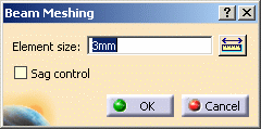
| 1. Click the Beam Mesher icon 2. Select the beam to be meshed.
The Beam Meshing dialog box appears. 3. Enter the desired Element size in the Beam Meshing dialog box. In this particular case, enter 3mm. |
|||||
|
New options are available under the activated Sag control option.
|
|||||
|
5. Click OK in the Beam Meshing dialog box. The 1D Mesh.1 feature now appears in the
specification tree. Note that now the corresponding Beam Property is
missing.
|
|||||
|
|||||
|
|||||


