Pad not Normal to Sketch Plane
| This task shows how to create a pad using a direction that is not normal to the plane used to create the profile. | |||
| Open the Pad6.CATPart document. | |||
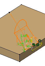
| 1. | Select the profile you wish to extrude. | ||
 |
|||
| 2. |
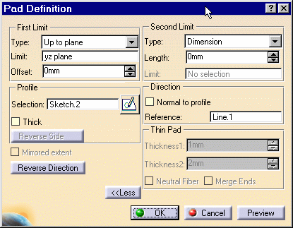
The Pad Definition dialog box appears and the application previews the pad to be created. |
||
|
|||
| 3. |
Set the Up to plane option and select plane yz. For more about this type of creation, refer to Up to Plane Pads. |
||
| 4. |
Click the More button to display the whole dialog box. |
||
| 5. |
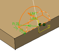
Uncheck the Normal to profile option and select the line as shown to use it as a reference. |
||
|
|||
|
The application previews the pad with the new creation direction. |
 |
||
| 6. |
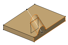
Click OK to confirm the creation. The pad is created. The specification tree indicates this creation. |
||
|
|||
|
|
|||


