Drafted Filleted Pad
| This task shows you how to create a
pad while drafting its faces and filleting its edges.
We recommend you the use of this new command to speed up your design. |
||||||||
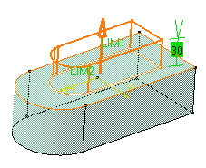
| Open the Hole1.CATPart document and sketch a profile similar to the one below. | ||||||||
| 1. | Quit the Sketcher and select the profile to be extruded. | |||||||
|
|
||||||||
| 2. | Click the Drafted Filleted Pad
icon The Pad Definition dialog box appears and the application previews the pad to be created. |
|||||||
|
|
||||||||
| 3. | Enter 30 as the length value. | |||||||
| 4. |
Selecting a second limit is mandatory. Select Pad1 top face as the second limit. |
|||||||
|
|
||||||||
| Note that planes can define second limits too. | ||||||||
| 5. | Let's go on with the draft
definition. Enter 7 as the draft angle value.
Drafting faces is optional. If you do not wish to use this capability, just uncheck the Angle option. |
|||||||
|
6. |
Check the Second limit option to define the neutral element. So, Pad1 top face is also used as the neutral element. |
|||||||
| 7. |
Enter a radius value for each edge type to define the three fillets.
Filleting edges is optional too. If you do not wish to use this capability, just uncheck the options. |
|||||||
| Clicking Preview previews the pad, the draft and the fillets and display them in the specification tree. If you have deactivated the draft or fillet options, the draft or the fillets are then displayed as deactivated features in the tree, i.e. with red parentheses. | ||||||||
| 8. | Click OK to create the features.
If you look at the specification tree, you will note that you have created:
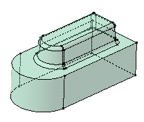
This means that for edition purposes, you need to double-click the appropriate feature. This is your new part: |
|||||||
|
|
||||||||
|


