 |
This task shows how
to instantiate PowerCopies once they have been created as described in Creating
PowerCopies.
There are two ways to do this:
- using the PowerCopy Instantiation menu item
- using a catalog
Furthermore, the use of the Replace viewer,
regardless of the instantiation type, is detailed. |
 |
Open the PowerCopyDestination1.CATPart document.
|
|
Using the menu item:
|
 |
-
Click the
PowerCopy Instantiation  icon or select the Insert -> Instantiate From Document menu item.
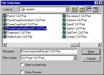
The File Selection dialog box is displayed allowing you to navigate
to the document or catalog where the power copy is stored.
|
|
|
|
-
Select the document containing the Powercopy, and
click Open.
Here we selected the PowerCopyStartResults1.CATPart
document.
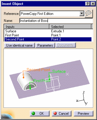
The Insert Object dialog box is displayed.
Use the Reference list to
choose the correct PowerCopy when several have been defined in the document.
-
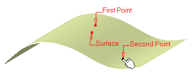
Complete the Inputs within the dialog box by selecting the adequate element in the geometric area.
|
|
|
 |
|
-
If needed, click on the Use identical name button to automatically
select all the elements with the same name.
This is especially useful when the input is the same one repeated
several time.
|
|
-
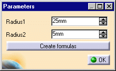
You can also click on the Parameters button to display the Parameters
dialog box and modify values.
Here we increased the Radius1 value to 25 mm.
-
Use the Create formulas button to automatically create a formula on
every parameters with the same name provided there are any.
-
Click OK.
|
|
 |
The Documents button lets you access the list of
documents (such as design tables) pointed by one of the elements
making up the Power copy.
If there are documents, the Documents dialog box opens and you can click
the Replace button to display the File Selection dialog box and navigate
to a new design table to replace the initial one.
When no document is referenced, the Documents button is grayed within the
Insert Object dialog box. |
|
-
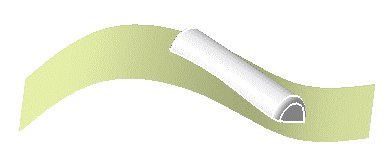
Click OK to create the PowerCopy instance.
The PowerCopy is instantiated in context, meaning its limits
are automatically re-defined taking into account the elements on which it
is instantiated.
|
|
 |
 | When instantiating from the same document, use the PowerCopy
object -> Instantiate contextual menu to display the Insert
Object dialog box directly. |
|
|
 | The  icon is always grayed when instantiating Power Copies. It is available
with User Features and allows you to create and modify URLs.
 |
|
|
Using the Replace Viewer
|
|
In some cases, when instantiating a powercopy, the replacing
element does not present the same sub-elements as the replaced element.
Therefore you need to clearly indicate in a specific dialog box, the
Replace Viewer, how to rebuild the geometry from the replacing element. In
the following example, the replacing sketch does not have the same number
of vertices as the initial sketch, and you are prompted to indicate on
what edge the filleted surfaces are to be created. |
 |
Open the PowerCopyReplace1.CATPart
document. |
 |
-
Expand the PowerCopy entry in the specification tree,
right-click the PowerCopy.1 feature, and choose PowerCopy.1
object -> Instantiate command.
-
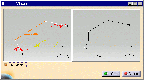
Select Sketch.2 to replace Sketch.1.
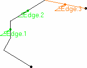
The Replace Viewer is displayed, showing to the left the initial
sketch and the edges selected to create the two fillets in the initial
geometry, and to the right the replacing sketch on which you are
prompted to specify edges.
|
|
|
|
-
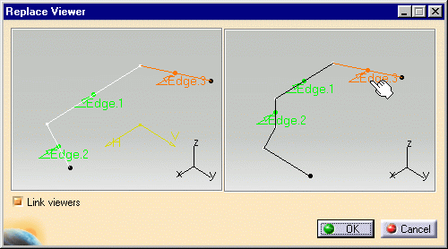
Select the edges on the replacing sketch.
|
|
|
|
-
Click OK in the Replace Viewer.
-
Select the XY plane, or click the Use Identical Name
to select it as the needed plane.
-
Click OK in the Insert Object dialog box.
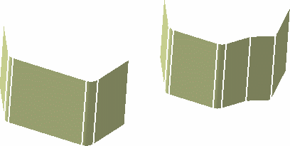
The PowerCopy is instantiated and the filleted surfaces are computed
as per the selection in the Replace Viewer.
|
|
|
 |
Make sure to select the edges as proposed in the Replace
Viewer. For example, you cannot invert Edge.1 and Edge.2 if Edge.3 remains
where specified in the example above. Otherwise, the system will not be
able to re-build the geometry based on these specifications, and the
Update Diagnosis dialog box will be displayed prompting you to edit the
geometry. |
 |

|


