Creating Splines
|
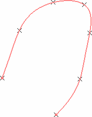
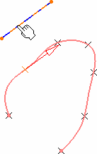
This task shows the various methods for creating spline curves. |
||||||||||||
|
Open the Spline1.CATPart document. |
||||||||||||
|
|
|||||||||||
|
||||||||||||
|
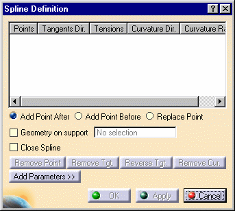
In the figure above, the spline was created |
|||||||||||
 |
||||||||||||
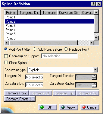
| There are two ways of imposing tangency and curvature constraints: | ||||||||||||
|
|
|||||||||||
|
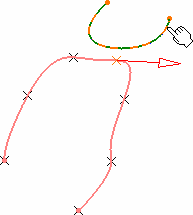 |
|||||||||||
|
Use the Remove Tgt., Reverse Tgt., or Remove Cur. to manage the different imposed tangency and curvature constraints. |
||||||||||||
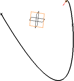 |
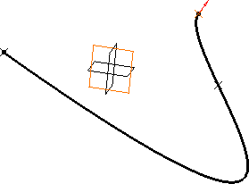 |
|||||||||||
|
Spline with a tangency constraint on endpoint (tension = 2) |
Spline with reversed tangent |
|||||||||||
|
||||||||||||
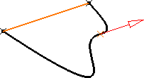
| The curvature direction is projected onto a
plane normal to the tangent direction. If you use the Create line contextual menu, and want to select the same point as a point already used to define the tangent direction, you may have to select it from the specification tree, or use the pre-selection navigator. |
||||||||||||
 |
 |
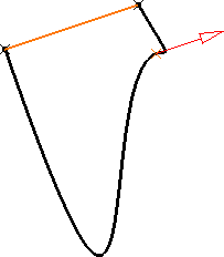 |
||||||||||
| Spline with tangency constraint | Spline with tangency
constraint and curvature constraint (radius = 50mm) |
Spline with tangency constraint and
curvature constraint (radius = 2mm) |
||||||||||
|
Note that for the Points Specifications, you must enter your information in the following order:
The fields become active as you select values. |
||||||||||||
The spline (identified as Spline.xxx) is added to the specification tree. |
||||||||||||
|
||||||||||||
|
||||||||||||
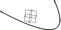 |
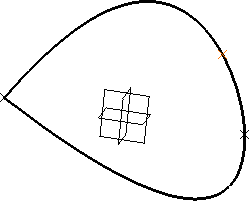 |
|||||||||||
| Spline with Close Spline option unchecked | Spline with Close Spline option checked | |||||||||||
|
||||||||||||
