Creating an Unfolded View
| This task shows how to create an unfolded view from a Sheet Metal
part. In
other words, you will extract drawings from the Sheet Metal
workbench (refer to Sheet Metal Design User's Guide).
An unfolded view is a projected view that is created from a Sheet Metal
part in order to include in a section certain angled elements. As a
result, the cutting plane may be bent so as to pass through those
features. |
|
| The Unfolded View command is active in the Generative Drafting workbench with version 5 Sheet Metal Design license. | |
| Before You Begin, make sure you customized the following settings:
Grid: Go to Tools->Options ->Mechanical Design -> Drafting option (Layout tab) and check the View name and Scaling factor options. 3D colors inheritance
|
|
| Open the GenDrafting_sheet_metal.CATPart document.
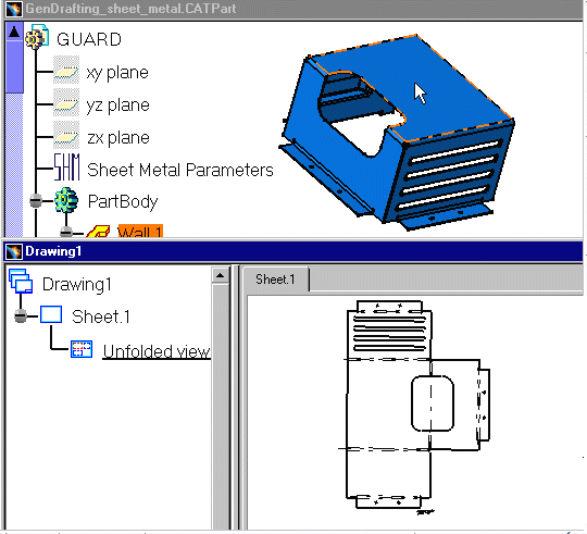
Tile the windows horizontally to see both your drawing sheet and your Sheet Metal part at the same time. |
|
| 1. From the Drafting
workbench, click the Unfolded View icon
|
|
| 2. Select a surface on the part. This will automatically use the sheet metal reference wall plane. | |
| If you prefer to specify which plane should be used, select
the plane in the Sheet Metal specification tree.
3. Click on the sheet. |
|
The unfolded view is displayed. It shows the axis lines resulting from bend axes, as well as bend limits. These axis lines and bend limits are represented as dashed lines. With Sheet Metal parts containing holes, the hole axes (center line) are also represented on the view. |
|
|
The unfolded view looks like this:
|
|
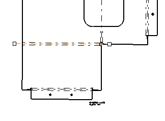
| 4. Select one of
the axis lines.
Manipulators appear, allowing you to modify this line.
|
|
|
|
|


