Creating
an
FD&T View
 |
This task shows how to generate a
view and the associated annotations from the 3D (Functional Dimensioning
and Tolerancing workbench).
An FD&T view is a view that is extracted from a 3D part that
is assigned 3D tolerance specifications and annotations.
|
 |
Before You Begin, make sure you customized the following settings:
Grid:
De-activate the Grid icon  from the Tools toolbar (bottom right).
View names and scaling factors:
Go to Tools->Options->Mechanical Design -> Drafting
(Layout tab) and check the
View name and Scaling factor options.
3D colors inheritance
Go to Tools->Options->Mechanical Design->Drafting option
(Generation tab) and un-check the 3D colors inheritance
option. |
 |
Before You Begin:
Tile the screen
horizontally:
Select Window -> Tile Horizontally option from
the menu bar.
In addition: make sure the standard used in the CATDrawing
document and in the CATPart (annotations) is the same. Otherwise, both the
view and the annotation will not be possibly generated.
Go
to Tools
-> Customize... menu bar options (Commands tab) and
select the Hide/Show 3D Annotations command. Then,
press the CLOSE switch button. The Hide/Show 3D Annotations
command automatically appears in the workbench. Make sure it is active.
OR
Go to Start
-> Mechanical Design -> Functional Dimensioning and Tolerancing
(menubar) and activate the Hide/Show 3D Annotations command. |
 |
1. Click the
View From 3D icon  from the Views toolbar (Projections subtoolbar). from the Views toolbar (Projections subtoolbar). |
 |
 |
|
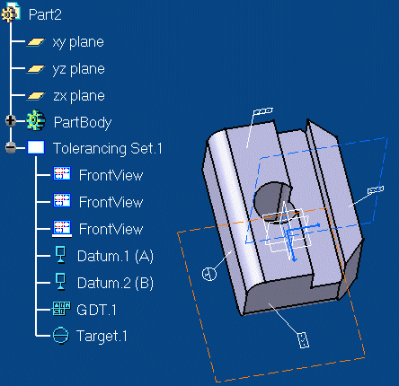
2. Select a
view from the 3D, either in the specification tree or on the part. In this
case, select the third Front View in the specification tree.

The view to be created is previewed (included annotations) on the
drawing. You cannot modify the view orientation.
3. Click on the drawing to create
the new view.

|
 |
 | The annotations can be moved or modified.
They are not associative to the geometry (except if you key in "c:
Force
Update", in which case, the view is updated and all the modifications
possibly applied to the annotations are lost). We advise you perform
modification on the 3D part. |
 | When you created a section cut in the 3D
instead of clicking on the drawing to generate the view, you can click on
another view in which the callout will be positioned. |
 | If you go to Tools
-> Customize... menu bar options (Commands tab) and
select the Unable/Disable 3D Annotation
queries command, press the CLOSE switch button and
make sure the Unable/Disable 3D Annotation
queries command is active, whenever you will
select an annotation, the surface this annotation is linked to will
highlight. Note you can also go to Start
-> Mechanical Design -> Functional Dimensioning and Tolerancing
(menu bar) and activate the Unable/Disable 3D Annotation
queries command. |
 | FD&T views cannot not be rotated. In other words, when you edit
the properties of this view (Edit -> Properties), the Angle
field is set to the gray color. |
|
|

|
|


