Creating a Section View / Cut (Planar Surface)
| This task will show you how to create
a section view / section cut using a planar surface or a wireframe plane in the 3D.
A section view / section cut is a view that allows sectioning through irregular objects, and thereby allows showing several features that do not lie in a straight line by offsetting or bending the cutting plane. |
| Before You Begin, make sure you customized the following settings:
Grid: View names and scaling factors: 3D colors inheritance |
|
Open the GenDrafting_part.CATPart
and the GenDrafting_front_view.CATDrawing
documents.
Before You Begin:
|
||
| 1. | Click the Drawing window, and click the Offset
Section View icon |
 |
|
 |
|||
| 2. |
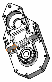
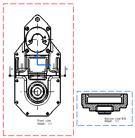
The section plane appears on the 3D part and moves dynamically on the part. The cutting profile is automatically displayed on the front view as well as a preview of the view to be generated. |
||
| 3. |
|
||
|
You may modify the hatching pattern by right-clicking the section view and selecting Properties from the contextual menu. You will then display a Properties dialog box in which you will either select a new hatching pattern or modify the graphical attributes of the existing hatching pattern. Please refer to Modifying a Pattern. |
||
|
|
|||
 Select a planar surface on the
3D part.
 Click to generate the view.