Creating a Geometrical Tolerance
| This task shows you how
to create a geometrical tolerance (annotation). You can also copy an existing geometric tolerance. You can set text properties either before or after you create the text.
Creating a Geometrical Tolerance |
||||||||
| Open the Brackets_views03.CATDrawing document. | ||||||||
| 1. Click
the Geometric Tolerance icon |
||||||||
 |
||||||||
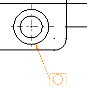
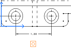
| 2. Select an element (geometry, dimension, text or point) or click in the free space to position the anchor point of the geometrical tolerance. | ||||||||
|

|
|||||||
|
 |
|||||||
|
 |
|||||||
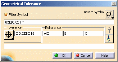
| 3. Move the cursor to position the geometrical tolerance and then click at the chosen location. The Geometrical Tolerance dialog box appears. | ||||||||

|
||||||||
| At this step, you can apply the parameter values of an
existing geometric tolerance to the tolerance you are creating: to do
this, simply select the existing geometric tolerance.
4. Select the Filter Symbol option to filter the available tolerance symbols according to the type of geometrical element you selected (if any). |
||||||||
|
If you did not select any geometrical element, the tolerance symbols will not filtered. |
||||||||
| 5. Specify the
tolerance type by clicking the Tolerance Symbol button and selecting the
appropriate symbol.
6. Type the tolerance value in the Tolerance value field, adding symbols as needed. To do this, position the cursor at the proper location in the field, and click the Insert Symbol button to choose the appropriate symbol. |
||||||||
|
You can add symbols to the tolerance and reference value as well as to the upper and lower text. |
||||||||
| 7.
Type the reference values in the Reference value fields, adding symbols as
needed.
8. To add a new geometrical tolerance, click the Next line arrow button and repeat steps 4 to 5. 9. Type the upper and lower texts in the appropriate fields. You may also add symbols if you want to.
|
||||||||
|
|
||||||||
The geometric tolerance is updated as you define values for each field. 10. Click OK when you're done. The
geometrical tolerance is created. |
||||||||

|
||||||||
| 11. You can add an
all-around symbol to the leader. To do this, select the geometrical
tolerance, right-click the yellow manipulator on the arrow and select All
Around from the contextual menu. |
||||||||
 |
||||||||
Leader orientation |
||||||||
The leader first segment can be perpendicular to the element
associated with the leader. For this, you can:
|
||||||||
Geometrical tolerance orientation |
||||||||
| The tolerance can be vertical. For this, hold the ctrl key before clicking in the drawing to position the tolerance (previous scenario, step 3). | ||||||||
|
||||||||

