 |
This task shows you how to create
a corner between two curves or between a point and a curve.
|
 |
Open the Corner1.CATPart
document.
|
 |
-
Click the Corner icon  . .
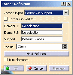
The Corner Definition dialog box appears.
|
|
-
Select a curve or
a point as first reference element.
-
Select a curve as second reference element.
The corner will be created between these two references.
-
Select the Support
surface. It can be a surface or a plane. Here we selected the zx
plane.
|
 |
|
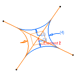
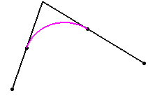
The resulting corner is a curve seen as an arc of circle
lying on a support place or surface. |
 |
 |
The reference elements must lie on this support, as well as the center of
the circle defining the corner. |
|
-
Enter a Radius
value.
|
 |
-
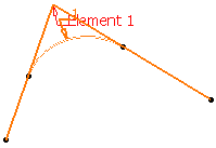
You can select the Corner
On Vertex check box if you want to create a corner by selecting
a point as Element 1 (Element 2 is grayed).
Select a direction or a support depending on the corner type you
chose.
|
 |
 |
|
-
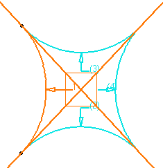
Several solutions
may be possible, so click the Next Solution button to move
to another corner solution, or directly select the corner you want in
the geometry.
|
 |
|
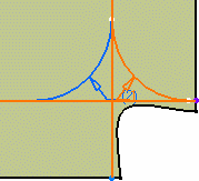
Not all four solutions are always available, depending
on the support configuration (if the center of one of the corners does
not lie on the support for example).
|
|
|
-
You can select the Trim
elements check box if you want to trim and assemble the two reference
elements to the corner.
-
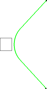
Click OK to create the corner.
The corner (identified as Corner.xxx) is added to the
specification tree. |
|
 |
When the selected curves are
coplanar, the default
support is the background plane. However, you can explicitly select any
support. |

|


