 |
This task shows how
to create a swept surface that uses an explicit profile.
|
|
You can create a
swept surface by sweeping out a profile in planes normal to a spine curve while taking
other user-defined parameters (such as guide curves and reference elements) into account.
You can sweep an explicit profile:
 | along one or two guide curves (in this case the first guide
curve is used as the spine) |
 | along one or two guide curves while respecting a spine. |
The profile is swept out in planes normal to the spine.
In addition, you can control the positioning of the profile while it
is being swept by means of a reference surface.
The profile position may be fixed with respect to the guide curve (positioned profile)
or user-defined in the first sweep plane (CATIA
P2 only).
|
 |
Open the Sweep1.CATPart document.
|
 |
-
Click the Sweep
icon  . .
The Swept
Surface Definition dialog box appears.
|
 |
|
-
Select the planar profile to
be swept out, that is the circle.
-
Select a guide curve.
|
 |
|
-
If needed,
select a spine.
If no spine is selected, the guide curve is implicitly used as the spine.
-
If needed, select a second guide curve.
-
If you want to control the position of the
profile during the sweep, you can select a reference surface. You can impose a reference
angle on this surface.
|
 |
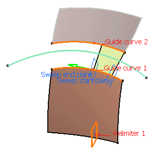
You can define relimiters
(points or planes) in order to longitudinally reduce the domain of the
sweep, if the swept surface is longer than necessary for example. |
 |
| |
Besides is an example with a plane as Relimiter 1.
When there is only one relimiter, you are able to choose the direction of
the sweep by clicking the green arrow. |
 |
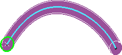
 | Relimiters can be selected on a closed curve (curve, spine, or
default spine). In that case, you are advised to define points as
relimiters, as plane selection may lead to unexpected results due to
multi-intersection. |
 | You can
stack the creation of the elements by using the contextual menu available
in either field. |
|
|
-
In the Smooth sweeping
section, you can check:
|
|
 | the Angular correction option to smooth the sweeping motion along the reference surface.
This may
be necessary when small discontinuities are detected with regards to the
spine tangency
or the reference surface's normal. The smoothing is done
for any discontinuity which angular deviation
is smaller than 0.5 degree,
and therefore helps generating better quality for the resulting swept
surface. |
|
 |
 |
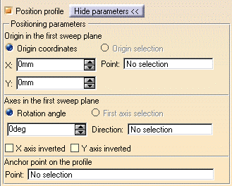
the Position profile. In CATIA
P2 only, if you want to manually position the profile, check the Position profile
button and click the Show parameters >> button to access a set of positioning parameters. |
|
 |
|
These parameters and the
graphic manipulators will allow you to position the profile in the first sweep plane.
 | Specify a positioning point in the first sweep plane by either entering coordinates or
selecting a point. |
 | Specify the x-axis of the positioning axis system by either selecting a line or
specifying a rotation angle. |
 | Select the X-axis inverted check box to invert the x-axis orientation (while
keeping the y-axis unchanged). |
 | Select the Y-axis inverted check box to invert the y-axis orientation (while
keeping the x-axis unchanged). |
 | Specify an anchor point on the profile by selecting a point. This anchor point is the
origin of the axis system that is associated with the profile. |
If you want to go back to the original profile, uncheck the Position
profile button. |
|
-
Click OK to create the swept surface.
The surface
(identified as Sweep.xxx) is added to the specification tree.
|
 |
 |
Generally speaking, the sweep operation has a derivative effect, meaning that
there may be a continuity loss when sweeping a profile along a spine. If
the spine presents a curvature continuity, the surface presents at least a
tangency continuity. If the spine presents a tangency continuity, the
surface presents at least a point continuity. |

|


