 |
This task shows how
to create fill surfaces between a number of boundary segments.
|
 |
Open the Fill1.CATPart document.
|
 |
-
Click the Fill icon  . .
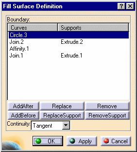
The Fill Surface Definition dialog box appears.
-
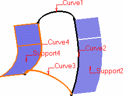
Select curves or surface edges to form a closed boundary.
|
 |
|
You can select a support surface for each curve or edge. In this case continuity will
be assured between the fill surface and selected support surfaces.
|
|
-
Use the combo to specify the
desired continuity type between any selected support surfaces and the fill surface: Point
or Tangent.
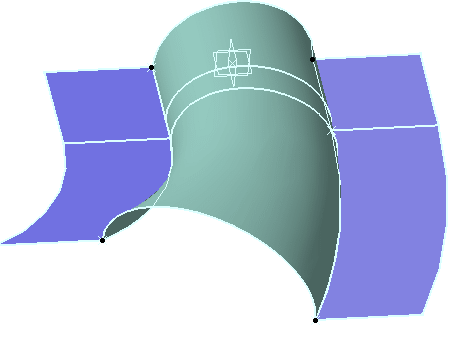
The fill surface is displayed within the boundary.
|
 |
|
-
You can edit the
boundary by first selecting an element in the dialog box list then choosing a button to
either:
|
|
 | Add a new element after or before the selected one |
 | Remove the selected element |
 | Replace the selected element by another curve |
 | Replace the selected support element by another support surface |
 | Remove the selected support element. |
|
 |
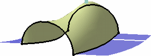
This point should lie within the area delimited by the
selected curves. If not, the results may be inconsistent.
|
|
-
Click OK to
create the fill surface.
|
|
The surface (identified as
Fill.xxx) is added to the specification tree. |
|

|

|
|
Filling surface with specified supports |
Filling surface with passing point (P2 only) |

|


