Updating an Assembly
| This section describes how to update
the whole assembly. Updating an assembly means updating its components as well as its constraints. The application lets you choose between updating the whole assembly or the components of your choice. |
||||||
| The option "Automatic switch to Design mode" is available for this command. For more about this option, refer to Access to geometry. | ||||||
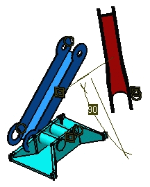
| The constraints are in black, indicating they need an update. The default color is black, but the application allows you to redefine the colors you want. To do so, refer to Customizing Constraint Appearance. | ||||||
|
||||||
| 1. | Select the Tools -> Options command, then
expand the Mechanical Design section to the left to access Assembly Design
options.
You can choose between two update modes within the Assembly Design workbench:
Note that this is a way of enhancing productivity: for instance, you can now use the automatic update mode when designing your parts in Assembly context, while having the Manual update mode activated for your assembly. You can also define whether you need to update the active level or all the levels. |
|||||
|
|
||||||
| 2. | Check the Manual option in the Update frame. | |||||
| 3. | Click OK to confirm and close the dialog box. | |||||
| 4. | Click the Update
icon |
|||||
| The assembly is updated. Graphic symbols are green, indicating that the constraints are valid. | ||||||
 |
||||||
To update only some components, select the components of interest and use the Update contextual command. Note however that applying the contextual command to a component may sometimes induce a general update if the assembly is a complex one made up of several components. |
||||||
|
To see what happens when an update operation fails, refer to Over-constrained Assemblies. See also Analyzing Updates. |
||||||

