Creating an Auxiliary View
|
This task will show you how to create an auxiliary view.
Many objects are of such shape that their principal faces cannot always be assumed parallel to the regular planes of projection. Creating an auxiliary view allows showing the true shapes by assuming a direction of sight perpendicular to planes that are perpendicular of the curves. This auxiliary view, together with the top view, completely describes the object. |
| Before You Begin, make sure you customized the following settings:
Grid: View names and scaling factors: 3D colors inheritance |
|
Open the GenDrafting_part.CATDrawing document.
|
||||
|
Before You Begin:
|
|||||
| 1. | Click the Auxiliary View icon |
 |
|||

|
|||||
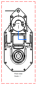
| 2. | Sketch the representation of the plane. In this case, click an edge on the right view. You could also click a point and then an edge. Both the 3D surface and the sketched plane are associative. The selected edge becomes a line that you can position where desired using the cursor. This line/callout will be automatically used as the plane. |
|
|||
| 3. | Click to position the callout.
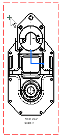
The reference plane is automatically positioned according to the selected edge. Positioning the auxiliary view callout amounts to defining the auxiliary view direction. |
.  |
|||
| 4. | Click to position the auxiliary
view.
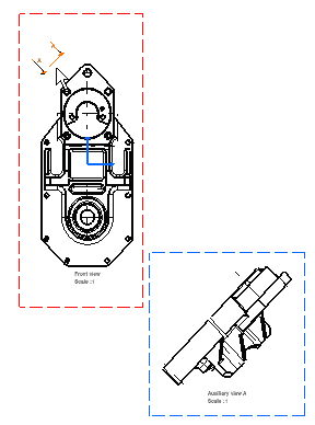
Before clicking, as you move the cursor within a zone perpendicular to the plane, a preview of the auxiliary view to be created simultaneously appears. This view will be automatically positioned accordingly. This is also true when creating a section view or a section cut. You can also move the cursor outside the
zone perpendicular to the plane and position the view where you want. |
||||
|
|||||
|
|
|
||||
|
|
|||||
