Creating Pivots
| Pivots are hinge
(conical join)
restraints applied to handle points of virtual parts,
which result in constraining the point to rotate around a given axis. They can be
viewed as particular cases of general hinge joins,
which allow a relative rotation between two points (in the Pivot case, one of the two points is
fixed, along with the pivot axis). Pivot objects belong to Restraint objects sets.
For the fixed point, the program automatically picks the handle of the virtual part. The user defines the pivot direction, and as a result the virtual part as a whole is allowed to rotate around an axis parallel to the pivot direction and passing through the fixed point. Make sure you fixed all the global degrees of freedom of your assembly, otherwise a global singularity will be detected at the time of the Static Computation (such a model is unsolvable). To allow you to easily correct the model (Static Analysis Cases only), the singular displacement of the assembly will be simulated and visualized after computation. When connected to deformable bodies, the virtual part will transmit the effect of the Pivot restraint collectively to the entire connected geometry.
|
|||||||||||||||||
Pivots can be applied to the following types of Supports:
|
|||||||||||||||||
|
This task shows how to create a Pivot on a virtual part.
|
|||||||||||||||||
| You can use the sample15.CATAnalysis
document from the samples directory for this task: a Finite Element Model containing a
Static or Frequency Analysis Case and created a Virtual
part.
Before You Begin:
|
|||||||||||||||||
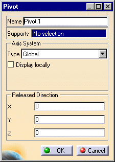
| 1. Click the Pivot icon The Pivot dialog box is displayed.
2. You can change the identifier of the Pivot by editing the Name field, if needed. The Axis System Type combo box allows you to choose between Global and User-defined Axis systems for entering components of the pivot axis.
3. Set the Axis system. 4. In the X, Y,
Z fields, enter the values corresponding to the components of the
pivot direction relative to the selected Axis system. |
|||||||||||||||||
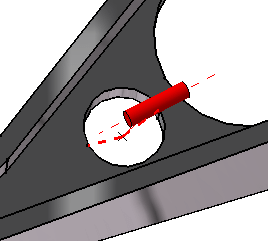
5. Select a virtual part. A symbol representing the pivot direction is displayed on the virtual part.
The visualized Pivot symbol orientation is automatically updated to reflect the modifications of the compass principal direction. 7. Click OK to create the
Pivot.
|
|||||||||||||||||
|
|||||||||||||||||
| Make sure the computation is finished before starting any of the following operations. | |||||||||||||||||
|
|
Products Available in Analysis Workbench
|
||||||||||||||||
|
|
|||||||||||||||||


