 |
This task shows how
to create boundary curves.
|
 |
Open the Boundary1.CATPart document.
|
 |
-
Click the Boundary icon  . .
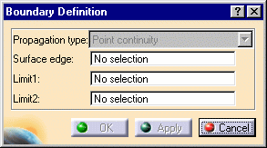
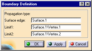
The Boundary Definition
dialog box appears.
|
 |
|
-
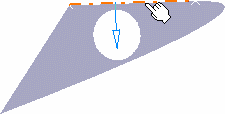
Select a Surface edge.
The boundary curve is displayed according to the selected
propagation type. |
 |
|
-
Use the combo to choose the
Propagation type:
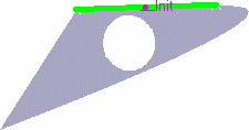
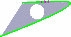
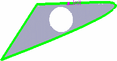
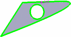
 | Complete boundary: the selected edge is propagated around the entire
surface boundary. |
 | Point continuity: the selected edge is propagated
around the surface boundary until a point discontinuity is met. |
 | Tangent continuity: the
selected edge is propagated around the surface boundary until a tangent discontinuity is
met. |
 | No propagation: no propagation or continuity condition is
imposed, only the selected edge is kept. |
|
|
 |
 |
|
No propagation |
Tangent continuity |
|
 |
 |
|
Point continuity |
Complete boundary |
|
-
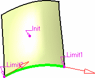
You can relimit the boundary curve by means of
two elements, a point on the curve for
example.
-
Click OK to create the boundary curve.
The curve (identified as Boundary.xxx) is added to the specification tree. |
 |
 | If you select the surface directly, the Propagation type no longer is
available, as the complete boundary is automatically generated. |
|
 |
|
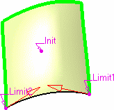
Provided
the generated boundary curve is continuous,
you can still select limiting point to limit the boundary.
|
|
|
Using the arrows you can then invert the limited boundary.
|
|
|
 | You cannot copy/paste a boundary from a document to another. If you
wish to do so, you need to copy/paste the surface first into the
second document then create the boundary. |
|

|


