 |
This task shows how to create a
surface by offsetting an existing
surface.
|
 |
Open the Offset1.CATPart document.
|
 |
-
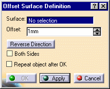
Click the Offset
icon  . .
The Offset Surface
Definition dialog box appears.
|
 |
|
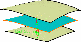
-
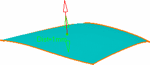
Select the surface to be offset.
-
Specify the offset by entering a value or using the graphic
manipulator.
-
An arrow indicates the proposed direction
for the offset.
The offset surface is displayed normal to the reference surface.
|
 |
|
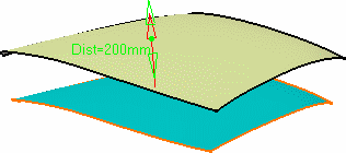
-
Click Apply to previews the offset
surface.
The offset surface is displayed normal to the reference surface.
|
 |

|
Depending on the geometry configuration and the offset
value, an offset may not be allowed as it would result in a debased
geometry. In this case, you need to decrease the offset value or modify
the initial geometry. |
|
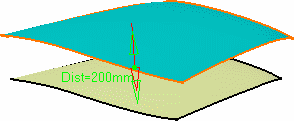
You can display the offset surface on the other side of
the reference surface by clicking either the arrow or the Reverse Direction
button.
|
 |
|
-
Check the Both sides button to
generate two offset surfaces, one on each side of the reference
surface.
|
 |
|
-
Click OK to create the surfaces.
The surfaces (identified as Offset.xxx) are added to the specification tree.
|

|
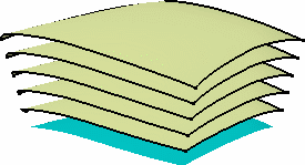
 | Use the Repeat object after OK
checkbox to create several offset surfaces, each separated from the initial
surface by a multiple of the offset value.
Simply indicate in the Object Repetition dialog box the number of
instances that should be created and click OK.
Remember however, that when repeating the offset it may not be allowed to
create all the offset surfaces, if it leads to debased geometry. |
|
 |
|
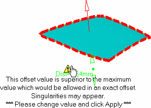
| Would the value be inconsistent
with the selected geometry, a warning message is displayed, along with
a warning sign onto the geometry. If you move the pointer over this
sign, a longer message is displayed to help you continue with the
operation. |
Furthermore, the manipulator is locked, and you need to modify the value
within the dialog box and click Apply.
|
 |
|
| The options set in the dialog box are retained when exiting then
returning to the Offset function. |
|

|