Creating a Roughness Symbol
| This task will show you how to create a roughness symbol. You can set text properties either before or after you create the roughness symbol. | |||||||||||||||||||||||||||||||
| Open the Brackets_views03.CATDrawing document. Create a dimension. | |||||||||||||||||||||||||||||||
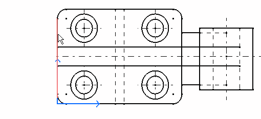
1. Click the Roughness Symbol icon
|
|||||||||||||||||||||||||||||||
 |
|||||||||||||||||||||||||||||||
| The Roughness Symbol Editor dialog box is displayed.
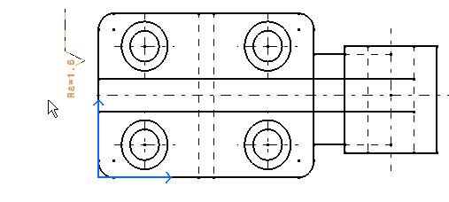
3. Enter values in the desired field(s). For example, Ra=1.6. 4. Click OK. |
|||||||||||||||||||||||||||||||
|
|||||||||||||||||||||||||||||||
|
|||||||||||||||||||||||||||||||
|
5. If needed, modify the roughness symbol position by dragging it to the required location. 6. Click in the free space to validate the roughness symbol creation. The roughness symbol is created. |
|||||||||||||||||||||||||||||||
 |
|||||||||||||||||||||||||||||||
|
|||||||||||||||||||||||||||||||
|
|||||||||||||||||||||||||||||||


