 |
This task shows how to create a support.
It may be either a plane or a surface.
This will
allow you to automatically reference a surface or plane as the supporting
element whenever you need one, when creating Lines for example. You will
no longer have to explicitly select the support element.
It will also allow you to create reference points on the fly on the
support, whenever you need a reference point to create other geometric
elements. |
 |
Open the WorkOnSupport1.CATPart document.
|
|
Creating a support from a surface
|
|
 |
-
Click the Work on Support icon  . .
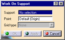
The Work on Support
dialog box appears.
|
 |
|
-
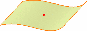
Select the surface
to be used as support element.
If a plane is selected, a grid is
displayed to facilitate visualization.
|
|
-
Select a point.
By default the surface's midpoint is selected.
|
 |
|
-
Click OK in the dialog box.
The element (identified as WorkingSupport.xxx) is added to the specification tree.
|
|
-
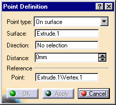
Click the Point icon  . .
The Point definition dialog box is displayed. The
Reference Point field is automatically filled in with the point selected
when defining the currently active working
support.
|
 |
|
Creating a support from a plane
|
 |
-
Click the Work on Support icon  . .
|
|
-
Select the plane to be used as support element.
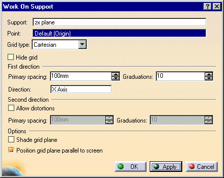
The Work on Support dialog box is displayed, allowing you to define the
plane:
|
|

|
|
By default, the Grid type is set to Cartesian, to define a Cartesian
plane.
|
 |
A grid can also be displayed to facilitate visualization.
You can hide it by checking the Hide
grid option.
|
|
-
Select a point, as the support plane's origin.
|
 |
By default the plane's origin is selected. Beware of the
plane representation not being located at the plane's origin. In this
case, the default point, really is displayed at the origin and therefore
not necessarily onto the plane representation. |
|
-
Define the First direction scale (H for
horizontal), by
setting Primary spacing and Graduations values.
-
If needed, select a direction to specify the H
direction.
You can right-click in the editable field to display the contextual
menu and define the direction (by defining its vector, creating a
line, and so forth).
-
If you wish, you can define another scale for the Second
direction scale (V for vertical), thus allowing distortions of the grid.
Check the Allow distortions option to activate the Primary
spacing and Graduations fields of the second
direction.
-
Check the Shade grid plane option to
visualize the support plane as a solid geometric element.
This is possible only if the View mode is adequate.
-
Check the Position grid plane parallel to screen
to reset the grid visualization parallel to the screen.
|
|
-
Click OK in the dialog box.
The element (identified as WorkingSupport.xxx) is added to the specification
tree.
|

|
 | By default the last created working support is displayed in red in
the specification tree.
Use the Set As Current/Set As Not Current contextual menu,
or the Working Supports Activity  icon, to define
which is the default current support that will be automatically
selected when entering a command that requires a working support.
 |
|
 |
|
 | Regardless of the type of working support created (surface or plane)
once you choose to work on the support, you can directly click onto
the support to create points. This capability is available with
commands such as point,
line,
spline, polyline,
and most commands where you need to select points as inputs. |
|
|
 | Working supports can be edited, updated, or deleted just as any other feature. |
|
|
 | Click the Snap to point icon  to snap the point being created onto the nearest intersection point on
the grid.
 |
|

|


